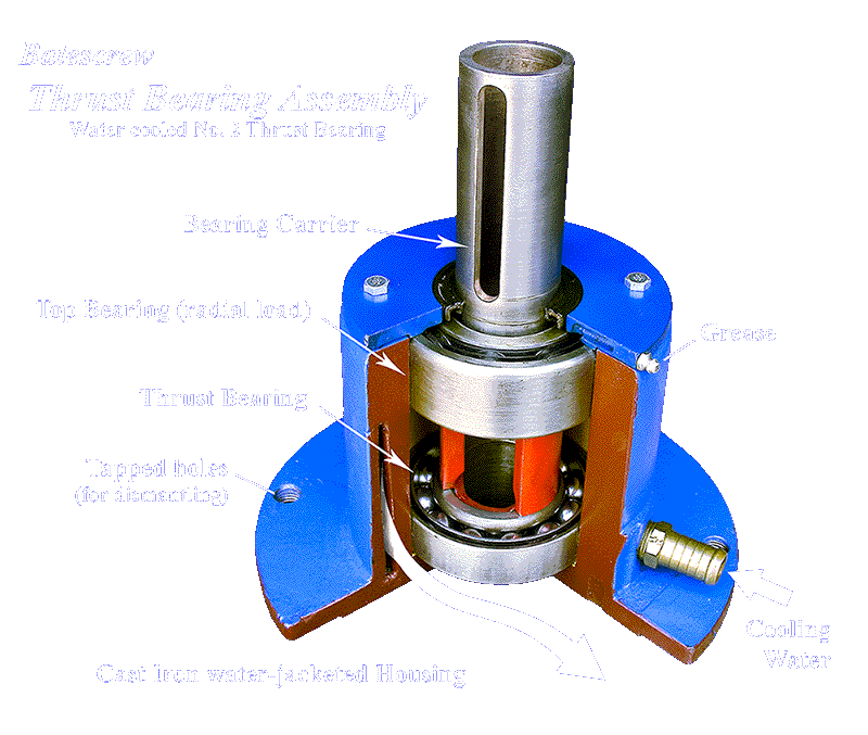
(The heavy duty model, size 6, has two tapered roller bearings, some models contain three or four bearings in tandem, as indicated in the table.)
A pump shaft, not shown, passes up through the Bearing Carrier, where a single drive key engages keyways in the shaft, the carrier and the drive coupling (or pulley).
The protruding upper end of of the pump shaft is threaded for a Top Nut, which transfers pump thrust down onto the carrier and thence to the lower bearing.
The top bearing supports radial loads from pulleys, drive shafts etcetera.
No. 1 Thrust Bearing: Apply one pump form a grease gun, to each of the two MFCG bearings, per month for continuous running or one pump every three months for intermittent running.
Bearings 2,3,4,5, 6, 7; in constant use: Apply two pumps from a grease gun, to the single nipple at top of the housing, every month.
Bearings 2,3,4,5, 6, 7; intermittent use: Apply two pumps every three months.
BEARING LIFE WILL BE SHORTENED by over greasing, indicated
by excessive accumulation of grease and dust beyond the seals.
CAUTION: When applying two pumps of grease, the first will enter
freely, go carefully with the second, if sudden resistance is felt - stop
immediately.
REPACKING BEARINGS After replacing bearings and seals (water cooled housings), fully re-pack each bearing with grease and fill one-third of the cavity between the bearings.
If there will be insufficient pressure for cooling water to reach an elevated housing, a special air-cooled housing or a separate thermo-siphon water cooling system should be used. Please consult Batescrew Technical Services Department for details.
sizes 4, 5& 6, are Mild Steel fabrications. Bronze castings or Stainless Steel fabrications may be specified for water cooled housings used in marine or corrosive applications.
2) Remove Top Nut and Drive Key
3) Remove flange bolts. (The entire bearing assembly can now be 'jacked off', if it is found to be frozen to the pump shaft.)
4) To remove a frozen housing, rotate it beyond the bolt holes, then screw over-size bolts into the threaded flange holes (indicated in photo above), jacking against the top of the discharge head or other mounting flange.
5) After removing the top Cover Plate, the two bearings and carrier may be pushed out of the housing, by screwing bolts into two threaded holes in the bottom of the housing. (These holes are plugged with Allen screws.)
Two entirely different methods are used for setting impeller height, via the Top Nut, depending on the type of pump - Axial Flow or Turbine.
1) AXIAL FLOW PUMPS Gently screw the Top Nut down, to the limit of its travel (raising impellers to the top of their housings), then back-off the nut two full turns. Lock the Top Nut by means of the grub screw, in whichever of the two tapped holes in the nut is closest to the keyway, slightly adjusting nut position so that the grub screw is seated in the bottom of the keyway.
2) TURBINE PUMPS The
vertical position of turbine impellers is more critical, requiring
impellers to be raised a specified distance from their lowest position
(Top Nut screwed clear of Bearing Carrier).
a) For pumps with less than 30 metres (100ft) of column: After
lowering the impellers as described above, screw the Top Nut down until it
can be felt to have fully taken up the weight of shaft and impellers
(impellers just clear of bottom seating), continuing to screw until the
shaft has been raised 2mm, then screw the Top Nut one more full
turn. Lock the Top Nut in the keyway, as described for axial flow
pumps above.
b) For pumps with more than 30 metres (100ft) of column:
Please obtain the necessary clearance from the Operation and Maintenance
Manual supplied with the pump, or contact Batescrew, quoting serial number
on the nameplate riveted to the discharge head.
Turbine clearances are calculated individually for each long pump, taking
account of:
1) Shaft stretch, governed by axial loading and length of line shaft; and
2) Differential contraction between the column (in the sun) and line shaft
(in shade), when cold water first enters the column.